Lab 3-1 Installing Visio and running tutorials
- Get out your Visio disk.
- Start your computer and log into an administrator account.
- Insert the Visio CD and run the installation.
- Complete the tutorials at: http://office.microsoft.com/en-us/visio/HA010837201033.aspx
Do Dis:
|
1.
Open
Visio 2.
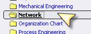
Notice
that there are a lot of options for drawings you can create. We want to draw
a network, so select Network |
|
|
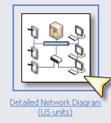
3.
Select
Detailed Network Diagram using US Units 4.
Visio
will open a blank page. The difference in templates is the shapes that open
with it. Look on the left. You’ll see bunches of shapes that can be used for
your network. 5.
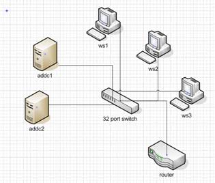
Let’s
create a simple star topology network. |
|
|
6.
Click
on Network and Peripherals and find the switch. It’s just a generic switch. 7.
Click
and drag it onto your drawing space. 8.
If
you’re creating a specific drawing using specific switches, you can download
shapes from companies like Cisco. 9.
If
you’re doing a general drawing, such as a proposal, there are accepted
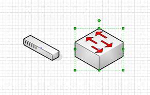
symbols that you would use. 10.
Click
on Network Symbols 11.
Find
the workgroup switch. Drag it over to your drawing board. Notice that it has
arrows that represent data sending and receiving. |
|
|
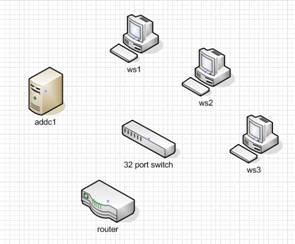
12.
Go
back to peripherals and drag over one server and one computer and one router.
Go ahead and click on the switch symbol, hit the delete key and delete it.
We’ll use symbols later. |
|
|
13.
To
make it easy you can copy shapes. Hold down the ctrl key on your keyboard and
click and drag the computer you brought over. Create three of them. |
|
|
14.
Now
lets label each thing. Click the switch and just start typing 32 port switch. Label the others as
shown. 15.
Let’s
create another Active Directory Server. Click, hold down control, and drag.
Rename it ADDC2 by double clicking on the words and typing. |
|
|
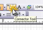
16.
Now
lets connect them together. Go up to the toolbar and select the Connector
Tool. 17.
Notice
that as you bring your mouse over the switch it highlights where you can
connect. 18.
Click
on the switch and drag the connector line to ws1. When ws1 gets a red box
around it, let go. 19.
Now
pick up and move ws1. What happens? 20.
Connect
the rest of the devices.
|
|
|
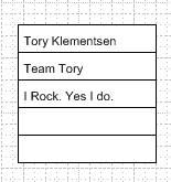
21.
Go
into Annotations in the shapes. Drag over the one named 5 ruled column for
annotation. 22.
Click
and type in your name, team name, and any other important information. 23.
In
EVERY network drawing you will annotate. This is a good place to indicate
things like how many workstations one computer represents, speed of network,
type of cable, etc. 24.
Now go
over to annotations and grab “Callout Bent”. Connect it to your router. 25.
Type
BootP Router. (That means the router will pass broadcast messages for DHCP and
for network booting.) |
|
|
26.
Save
your drawing. It will save as a VSD file (a visio desktop file). That’s good
for opening it and modifying it later, but if you want to put it into another
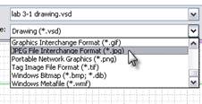
program you need to export it. 27.
Now
let’s save it as a JPG. Note that once you do this, you won’t be able to change
the JPG and any changes you make to the VSD won’t go to the JPG. 28.
Go to
fileàsave as… and select Jpeg. Ta da! |
|
|
29.
Now
create a new document and do the following 30.
Go
under FileàShapesàNetwork and note that there are a LOT more network shapes. Select a few
and poke around. 31.
Go to www.visiocafe.com and download the
following shape packets: a.
Dellfull.zip b.
Microsoft
Network Equipment Shapes 32.
Now
using the Network shapes and the Building Plan shapes, draw this room! |
Each
person turn it in! |