Lab 1-7 Testing Power Supplies
Objectives
7 Identify some dangers involved in Power Supplies.
7 Identify and diagnose common power supply problems.
7 Test a power supply using a power supply tester.
7 Test connectors on the power supply.
Materials Required
7 Power supply
7 Power supply tester
7 Different connectors on power supply
7 Multimeter
Directions
- Get a power supply tester from me (check it out).
- Read the accompanying instructions on how to test your power supply.
- Get three power supplies from the cupboard. Do not plug it in!
- Test each of the power supplies in the following manner
- Test the P1 connection
- Test each of the molex connectors
- Test the ATX connector, if present
- Test the SATA connectors
- Test the floppy connector, it present
- Fill out the table below
|
Power Supply Brand |
Wattage rating |
P1 test |
# Molex connectors |
Molex tests (pass/fail, note any that fail) |
# ATX connectors |
ATX test |
# floppy connectors |
Floppy connectors Test |
|
|
|
|
|
|
|
|
|
|
|
|
|
|
|
|
|
|
|
|
|
|
|
|
|
|
|
|
|
|
7 If any of the power supplies completely fails, throw it away (ensuring that you’ve tested others first to make sure you’re using the tester correctly).
7 If any of the power supplies has bad connectors but the P1 works, get a piece of tape and mark the bad connectors.
7 If any power supplies has all of a specific kind of connector fail, throw it away
- Now open up your lab computer, return your power supply tester, check out a multimeter.
- The first step in using the multimeter to perform tests is to select the proper function. For the most part, you never need to use the current function of the multimeter when working with computer systems; however, the voltage and resistance functions can be very valuable tools.
- In computer troubleshooting, most of the tests are DC voltage readings. These measurements usually involve checking the DC side of the power-supply unit. You can make these readings between ground and one of the expansion-slot pins, or at the system board power-supply connector.
- It is also common to check the voltage level across a system board capacitor to verify that the system is receiving power. The voltage across most of the capacitors on the system board is 5V (DC). The DC voltages that can normally be expected in a PC-compatible system are +12V, +5V, –5V, and –12V. The actual values for these readings may vary by 5% in either direction.
Normal practice is to first set the meter to its highest
voltage range to make certain that the voltage level being measured does not
damage the meter.
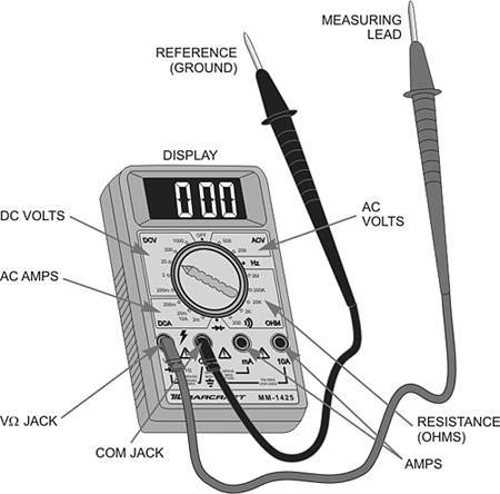
10. The DC voltage function is used to take measurements in
live DC circuits. It should be connected in parallel with the device being
checked. In a PC system, this typically means connecting the reference lead (black lead) of the meter to a ground
point and the measuring lead
(red lead) to a test point to take a measurement, as illustrated in the figure
below:
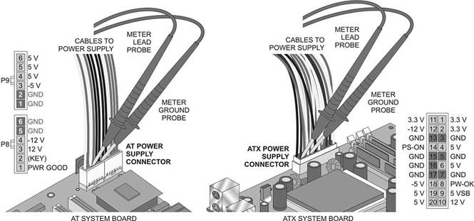
11. Note that on the side there is a label
of what each of the cables in the P1 does.
12. Set your multimeter to DC volts 3.3.
You’re telling it what you’re testing when you do this.
13. With the power off, connect the meter
lead probe to the 3.3v connector on the power supply connector as shown in the
second picture.
14. Connect the meter ground probe to the
ground on P1.
15. Ensure that the multimeter is turned
on and set to the correct settings. Set it down on the table with the probes in
the power supply.
16. Plug
in the power supply and turn it on. Without touching anything, write down the
reading you get below:
17. Turn off the machine, unplug the
power, remove the probes.
18. Do the same for the following
positions and record the readings
|
Voltage |
|
Voltage |
|
Voltage |
|
|
3.3 |
|
-5 |
|
5 |
|
|
12 |
|
-12 |
|
5 |
|
Remember to reset the
multimeter each time to the proper reading.
Testing Resistance
1. The second most popular test is the resistance test, or continuity
test.
2. Failure to turn off the power when
making resistance checks can cause serious damage to the meter and can pose a
potential risk to the technician. Resistance checks require that you
electrically isolate the component being tested from the system. For most
circuit components, this means desoldering at least
one end from the board.
3. The resistance check is very useful in
isolating some types of problems in the system. One of the main uses of the
resistance function is to test fuses. You must disconnect at least one end of
the fuse from the system. You should set the meter on the 1 k ohm resistance
setting. If the fuse is good, the meter should read near 0 ohms. If it is bad,
the meter reads infinite. The resistance function also is useful in checking
for cables and connectors. By removing the cable from the system and connecting
a meter lead to each end, you can check the cable's continuity conductor by
conductor to verify its integrity.
4. An electrical short
is a condition where electrical current is given a path of flow around a
designated component. In some cases, the short may be a complete bypass to a
ground point so that no components receive current to operate with. On the
other hand, an open is a condition that is
created when no path for electrical current is present, such as when a
connector comes loose or a component burns out.
5. Get one of our older motherboards.
6. Carefully locate a fuse and remove it.