Lab 1-2 Basic Electrical
Circuits
|
Requirement |
Check |
|
Created circuit |
|
|
Added switch |
|
|
Drawing of circuit |
|
|
Measured voltage |
|
|
Measured amps |
|
|
Answered questions |
|
|
Cleaned up station |
|
Objective
The objective of this lab exercise is to demonstrate and
define basic concepts and terminology related to the study and use of electricity.
After completing this lab exercise, you will be able to:
7 _ Create a simple switched circuit.
7 _ Describe the relationship among voltage, amperage, ohms,
and wattage.
7 _ Use a multimeter to measure voltage and amperage.
Materials
Required
7 _ One 9-volt battery
7 _ Electronic Playground and Learning Center
7 _ Four pieces (two short, two long) of standard-grade
electrical wire
ACTIVITY
Creating a circuit
- Connect your 9volt Battery to the board.
 Take
your long wires.
Take
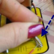
your long wires.- Attach one to LED2s first lead (3). To attach,
bend the spring, slip the exposed end of the wire in between the springs.
- Take the end of that wire and attach it to the
first spring on the battery (26)
- Now attach another wire between 4 and 27.
- What happens?
7.
Why?
Creating a Circuit with a Switch
1.
Disconnect your wires
from the battery.
2.
Connect one long wire
from 3 to the 10kΩ connector. Notice that you see a little resistor
there. A resistor resists or slows
the flow of energy. Remember that.
3.
Now connect one long
wire from 4 to 26.
4.
Take your two small
wires. Connect one from 27 to 56. Push the button. What happens?
5.
Why?
6.
Where do you need to
connect the other small wire to create a circuit controlled by the switch?
7.
Not move your wires
from the 10kΩ to the 1kΩ and push the switch.
8.
Turn on the light and
what happens? Is the light brighter, or dimmer?
9.
Why?
10.
Which of those
resistors slows the flow of energy down more?
11.
What do you think will
happen if you attach the leads to the 100kΩ resistor?
12.
This is Ohms Law in action! Ohms law states
that
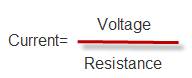
Current= voltage divided by
resistance…or the higher the resistance, the lower the current flows. If you
have lower resistance, the faster the current can flow. Voltage is what makes
the current flow. Lower resistance=brighter LED.
13.
Look at each of your
resistors very closely. What do you notice about them?
14.
Draw the
following resistors and label the colors of their bands
|
Resistor |
Drawing |
|
1kΩ |
|
|
10kΩ |
|
|
100kΩ |
|
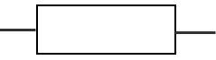
The color bands tell you what the resistor is.
·
The first ring is the first
digit of the resistor’s value
·
Second ring is the
second digit of the resistor’s value
·
Third ring tells you
the power of ten to multiply by (or the number of zeroes to add)
·
Fourth ring tells you
the construction tolerance. Most have a gold band for 5% tolerance, which means
that it is guaranteed to offer resistance within 5% of the marked value. (So a
100kΩ transistor with a gold band would offer resistance from 95 to
105Ω).
Color table
|
Color |
Value |
|
Black |
0 |
|
Brown |
1 |
|
Red |
2 |
|
Orange |
3 |
|
Yellow |
4 |
|
Green |
5 |
|
Blue |
6 |
|
Violet |
7 |
|
Gray |
8 |
|
White |
9 |
So a resister that had a bands, in
order: red, violet, orange, gold would be translated as
27X103=27000Ω with a 5% tolerance.
- In the
space provided below, draw a diagram demonstrating the flow of electricity
in the circuit you have created. Be sure to note the direction of the
current’s flow.
Measuring voltage
1.
Configure your
multimeter to measure the voltage of your circuit.
a.
Connect the red lead
to the VΩmA jack
b.
Connect the black lead
to the COM jack
2.
Attach the +/- leads from your multimeter to the respective +/-
sides of the battery (26 and 27). You can just touch the wires connected to
those positions.
3.
Turn the dial on your
multimeter to the closest voltage measurement you expect to see (hint…this is a
NINE volt battery).
4.
What voltage do you
see on the window (it’ll change, but should settle within a few seconds)?
5.
Now with the help from
a friend, take the leads and touch the wires leading out of 3 and 4 by the
light. Have someone push the switch. What is the voltage?
6.
Why is it different
from the answer you got above? What is between the battery and the LED?
7.
Change the resistance
from 10kΩ to 1kΩ. Now what is the voltage with the switch on?
Measuring amps (current)
1.
Amps are measured with
the current running, since it’s a measurement of current.
2.
Configure your
multimeter to measure the amps of your circuit.
a.
Plug in the red wire
to the VΩmA jack
b.
Plug in the black wire
to the COM jack
c.
Turn the dial to the
Amp area (see directions…hint, Amp starts with A) closest to the amperage you
expect to find. If you don’t know, set it to the highest one and change until
you get a reading that seems reasonable.
3.
Have a friend hold
down the switch.
4.
Touch the leads to 3
and 4. Record the amperage.
5.
Now let go of the
switch and what readings do you get? Why?
6.
Now take and touch the
leads (without pressing the switch) to the wires at 55 and 56. What happens?
7.
Why?
Because of this you must
be very careful when testing amperage in a live circuit because you CAN
complete that circuit. Your multimeter
must have a high enough rating to handle the current.
Review Questions
Circle True or
False.
1. Resistance is measured in ohms. True / False
2. A switch can act as a break in a circuit. True / False
3. AC is the acronym for ampere. True / False
4. A multimeter can measure only voltage. True / False
5. In a circuit, amps and volts are always the same amount
when measured. True / False
6. Describe the difference in multimeter placement for
measuring volts and amps.
Lab
Notes
7 What does AC mean?—Alternating
current (AC) is current that cycles back and forth rather than traveling in
only one direction. Normally between 110 and 125 AC volts are supplied from a
standard wall outlet.
7 What are amps?—Amps
are units of measurement for electrical current. One volt across a resistance
of one ohm will produce a flow of one amp.
7 What are volts?—A volt
is a measure of electrical pressure differential. A computer power supply
usually provides four separate voltages: +12 V, -12 V, +5 V, and -5 V.
7 What is wattage?—Wattage
is a measure of the total amount of power that is needed to operate an
electrical device.
7 What are ohms?— An ohm is the
standard unit of measurement for electrical resistance. Resistors are rated in
ohms.